Leakages at the Connecting Part Between Flanges & Reducers in Quench Boilers
Posted: 01/25/2022 07:25:15 Hits: 31
Abstract: Since April 2016, there have been frequent leaks and fires at the connecting part between the flange and reducer of the cracking furnace quench boiler in 220 kt/a ethylene unit of China National Petroleum Dushanzi Petrochemical. Through various inspections and analyses, it is found that the stress on the connection part at the leakage position could not be eliminated. The large gap between the sealing surfaces of flanges, improper installation position of the insulation and the improper insulation installation at the lower furnace tube are the causes of the above problem. By taking countermeasures, the hidden danger of leakage at the flange connection of the reducer was successfully eliminated.
The function of the quenching boiler of the cracking furnace of the ethylene plant when the cracking furnace is in operation is to rapidly quench the high-temperature cracked gas to stop the secondary reaction in the cracked gas and to recover the waste heat of the cracked gas to generate ultra-high pressure steam.
American Lummus technology was introduced for 220 ktla ethylene plant Dushanzi Petrochemical Company of China National Petroleum and Gas Corporation (hereinafter referred to as Dushanzi Petrochemical), with an initial production scale of 140 kt/a. 2 sets of quenching boilers with conical heads are adopted for each cracking furnace of No.1 to No.5 cracking furnaces (SRT-IV HS types). In 2002, 2 sets of SRT-VI HS furnaces (No.6 and No.7 furnaces) were added, each of which used 4 sets of bathtub-type double-jacketed quenching boilers. After the renovation and expansion, the annual production capacity of the plant will reach 220 kt. No.6 and No.7 furnaces were put into use in September 2002. Since 2016, leakage occurred at the connecting part between flanges and reducers of the quench boiler, which seriously affected the stable operation of the device. The reasons for the leakage at the connecting part between flanges and reducers of quench boilers and the use status after the repair were analyzed and discussed in this article. Table 1 shows the design parameters of the bathtub type quench boiler.
Table 1 The design parameters of the bathtub type quench boiler
| Items | Shell pass (boiler feedwater) | Tube pass (cracking gas) |
| Working pressure/MPa | 13.000 | 0.072 |
| Design pressure/MPa | 14.28 | 0.35 |
| Working temperature/℃ | 328.0 | Inlet 825.7 and outlet 376.9 |
| Design temperature/℃ | 370 or 340 | 900, 500 , 450 or 650 |
| Heat exchange area/m2 | 76.1 | |
| Number of tubes/pieces | 50 | |
| Specifications | Oval tubes Φ123 mm x72 mm x11 mm 15Mo3 | Inner tubes Φ51 mm x 5 mm, 15Mo3 |
| Outer tubes Φ73 mm × 5.6 mm, A106 | ||
1. Leakage analysis of the connecting part between flanges and reducers in quenching boilers
Since April 2016, connecting parts between flanges and reducers of four sets of quench boilers for the No.6 cracking furnace have often leaked and caught fire.
From April to August 2016, a fire occurred at the connecting part between flanges and one end of reducers of the 4 groups of quench boilers for the No.6 cracking furnace (Figure 1), and then the furnace was shut down and the flange gasket was replaced. Meanwhile, it was found that the sealing surfaces of 4 sets of flanges of quenching boilers were deformed. A metal wire packing with a fire retardant gasket and a metal wound wire gasket without an inner ring were adopted for joint sealing.
In June 2017, in the feeding process of the No.6 cracking furnace, there were leakage and fire at the connection part between the flange and one end of the reducer for the quench boiler. When tightening the connecting bolts, it was found that some of the bolts were deformed and broken.
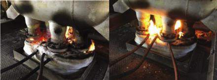
Figure 1 The leak and fire on site
1.1 The cause analysis of the leakage
After inspection and analysis, the reasons for the leakage are as follows:
1) The stress on the connection part of the flange at the leakage position could not be eliminated. Since the bathtub body at the lower part of the quenching boiler was used as the installation reference surface, the lower flange was always subjected to downward pulling stress.
2) The gap between the sealing surfaces of flanges was too large.
3) The thermal insulation installation position at the reducer and the thermal insulation installation form at the lower furnace tube were improper.
1.2 Measures to prevent leakages
Before the cracking furnace was repaired, measures are formulated according to the analysis of the cause of the leakage in the early stage.
1) It is found that the length of the connecting joint of the reducer at the lower part of the quench boiler is 550 to 580 mm after inspection, which is 20 mm to 50 mm shorter than the standard length of the sub-section, that is 600 mm. The joint of the furnace tube is made from 20CB2Ni. The methods of eliminating pulling stress of the joint of the furnace tube are to change the length and material of the joint. A length of 660 mm is adopted and the actual welding length is 650 mm. The material was replaced with 35Cr45Ni. Figure 2 shows the installation position of the joint.
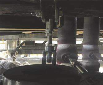
Figure 2 The installation position of the connecting joint
2) It is found that the splint of the lower furnace tube's short joint was deformed, with an angle of 10 after inspection. The function of the splint is to install constant force springs at both ends to clamp the furnace tube, so that the spring could adjust the furnace tube. After overhaul, restored it to its natural horizontal state.
3) The flange lining sleeve was parallel to the sealing surface. When the fire-resistant gasket was originally installed, the external flange could not play a sealing role. The bolts could not press the external sealing surface due to the great thickness of the fire-resistant gasket, resulting in the leakage of the flange. In this overhaul, the flange lining sleeve of the reducer was reduced by 5 mm, so that the fire-resistant gasket could properly seal (Figure 3).
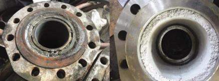
Figure 3 Repair of the sealing surface of the flange
4) Changed the installation position of the insulation at the joint of the reducer. The specification of flange bolts at the connection part are M20 x 142, and they are made from 20Cr1MoVNBI. The insulation installation position was lowered by 50 mm, so that the bolts and nuts were exposed to the air, and the heat could be dissipated to prevent the bolts from creeping in a high temperature, resulting in a decrease in bolt strength (Figure 4). Similarly, the splint of the lower furnace tube should also be exposed to the air.
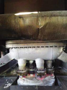
Figure 4 Insulation installation locations on site
Verification
From the feeding on July 30, 2017 to the stopping of feeding on October 28, the No.6 cracking furnace has been running smoothly for 91 days, setting a new high for the No.6 cracking furnace's operating time. At the same time, the cracking furnace process was optimized; the special care of the cracking furnace was strengthened, and the leakage at the joint of the reducer of the quench boiler was fundamentally solved.
Post URL: https://www.landeepipefitting.com/leakages-at-the-connecting-part-between-flanges-reducers-in-quench-boilers.html
Landee is a professional industrial pipe fitting manufacturer and be well accepted by customers all over the world, we has been producing Pipe Fitting for a variety of applications since 1985. welcome to access our website: https://www.landeepipefitting.com.
Previous: The Cause Analysis of Perforated Elbows for Cracking Furnaces
Next: Research on Cold & Hot Forming of S31254 180° Elbows
Next: Research on Cold & Hot Forming of S31254 180° Elbows
