Abstract
During the operation of a nuclear power plant, repeated leakage occurred at the outer casing elbow of the double-walled pipe in the hydrogen supply system. To determine the cause, the cracked elbow was examined through macroscopic inspection, microstructural analysis, chemical composition testing, hardness measurements, and other investigative methods. The results indicated that stress corrosion cracking had developed in the stainless steel elbow. Based on these findings, corresponding improvement measures were implemented, which effectively resolved the leakage during power operation. This case provides a valuable reference for addressing similar problems in other units.
1. Failure Overview
The hydrogen production and distribution system (SHY) uses a double-walled pipeline made of stainless steel (304L). During normal operation, the inner pipe carries hydrogen, while the annular space between the inner and outer walls of the casing is filled with high-purity nitrogen at a pressure slightly above atmospheric. The system is responsible for producing, storing, and distributing the hydrogen required for the safe operation of the nuclear power plant.
During routine plant operation, a crack and subsequent leakage occurred at the outer casing elbow of the SHY pipeline located in the GB trench, just before the branch line connecting to the No. 2 conventional island. A total of 14 leakage points were identified. The leaks were concentrated near the elbow welds. Rust stains were visible on parts of the outer casing surface, and uniform corrosion was observed at the weld locations. The service environment of some sections of the pipeline is particularly harsh. Nearby exhaust pipes intermittently release high-temperature steam, and corrosion becomes more severe closer to the steam discharge outlet. The GB trench is located upstream of the venting point for the No. 2 conventional island. It is suspected that chloride deposits have accumulated on the outer surface of the casing, contributing to the observed corrosion damage.
2. Macroscopic Analysis
2.1 Visual Examination of Elbows
Corrosion marks were observed on the outer surfaces of Elbows No. 1 and No. 2. Liquid penetrant inspection revealed cracks in both outer casing elbows. The cracks and corresponding leakage points were located approximately 10 mm from the weld fusion line, with lengths ranging from 10 to 20 mm. Based on these findings, it is preliminarily concluded that the cracks are situated within the heat-affected zone (HAZ) of the weld. Corrosion was also noted on the outer surface of Elbow No. 3; however, no defects were detected in this elbow by liquid penetrant inspection.
2.2 Dimensional Analysis of Elbows
The three elbows were cut in half using wire electrical discharge machining (EDM) for sampling and further analysis. A significant difference in wall thickness between the inner and outer arcs of the elbows was observed. Thickness measurements were taken at both the inner and outer bends, and the average values are presented in Table 1. In all three elbows, the wall thickness at the inner bend was consistently greater than at the outer bend, suggesting that the elbows were likely formed by a cold-bending process.
Table 1 Wall Thickness Measurements of Inner and Outer Bends of the Three Elbows
Measurement Position | Elbow No. 1 (mm) | Elbow No. 2 (mm) | Elbow No. 3 (mm) |
Inner Bend | 3.242 | 3.421 | 3.162 |
Outer Bend | 2.822 | 2.506 | 2.381 |
2.3 Surface Examination of Tees and Straight Pipes
Corrosion traces were observed on the base material near the weld area of the outer casing on both the tees and straight pipes. Liquid penetrant testing was performed on their surfaces, and no defects were detected.
3. Chemical Composition Analysis
The chemical composition of the base material from Elbow No. 2 (Sample A) and a section of straight pipe (Sample B) was analyzed in accordance with GB/T 11170-2008, as illustrated in Figure 1. The results were compared with the standard composition of 022Cr19Ni10 specified in GB/T 20878-2007. The comparison is presented in Table 2. The compositions of both the cracked elbow and the straight pipe base material comply with the specified limits in GB/T 20878-2007, indicating no abnormalities in chemical composition.
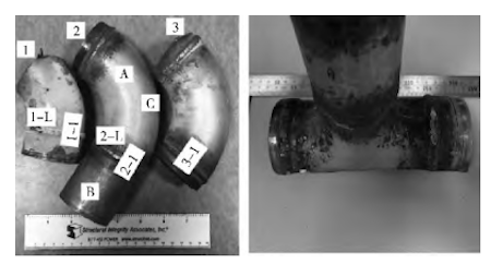
Figure 1 Sampling locations for chemical composition analysis
Table 2 Chemical Composition of Elbow and Straight Pipe Materials (wt.%)
Element | C | Si | Mn | S | P | Cr | Ni |
Elbow A | 0.021 | 0.36 | 1.19 | 0.006 | 0.036 | 18.34 | 8.02 |
Straight Pipe B | 0.020 | 0.64 | 1.19 | 0.005 | 0.033 | 18.27 | 8.03 |
Standard Limit | ≤0.030 | ≤1.00 | ≤2.00 | ≤0.030 | ≤0.045 | 18.00–20.00 | 8.00–12.00 |
4. Metallographic Inspection
4.1 Base Material Metallographic Examination
Samples were extracted from various areas of the three elbows, as depicted in Figure 1. Metallographic analyses were conducted on these samples in accordance with GB/T 13298-2015. The specimens were etched using a 4% nitric acid solution. The metallographic results indicated no abnormalities in the weld zones of Elbows No. 1, No. 2, and No. 3. Granular carbides were observed precipitating at the boundaries between the weld ripple zones and the base material zones on both the inner and outer surfaces of the elbows. Additionally, slip lines were present on the inner and outer surfaces of the base material zones, suggesting that the elbows underwent cold working without subsequent heat treatment or with improper heat treatment. Such cold working deformation can lead to residual tensile stresses within the material.
The metallographic structures of the 1-1 section sample from Elbow No. 1, the 2-1 section sample from Elbow No. 2, and the 3-1 section sample from Elbow No. 3 were found to be similar. Taking the 1-1 section as an example, as shown in Figures 2(a) to 2(d):
- The weld zone comprises austenite and dendritic ferrite.
- The weld ripple zone on the elbow side consists of austenite, carbides, and a small amount of ferrite distributed along the grain boundaries near the fusion line; no slip lines were observed in this zone.
- The base material zone of the elbow contains austenite and carbides, with numerous slip lines present on the outer surface.
The metallographic structures of the outer surfaces of the Elbow No. 2 Sample A and the Straight Pipe Sample B are presented in Figures 2(e) and 2(f), respectively:
The outer surface of Sample A (elbow) exhibits austenite with precipitated granular carbides along the grain boundaries.
The outer surface of Sample B (straight pipe) displays austenite.
The metallographic structures of the C-section sample, taken along the axial direction at the apex of the outer bend of Elbow No. 2, are shown in Figures 2(g) and 2(h):
- The outer surface of the C-section consists of austenite and carbides, with a high density of slip lines.
- The inner surface of the C-section also contains austenite and carbides; however, the slip lines are less dense and shallower compared to those on the outer surface.
4.2 Metallographic Examination of the Crack Section
A metallographic specimen was prepared from the 1-L area of Elbow No. 1, which exhibited cracking, along the wall thickness direction. The overall metallographic appearance is shown in Figure 3(a). The crack extends from the outer surface into the base material in a tree-like pattern. Upon reaching approximately half the wall thickness, the crack bifurcates into three branches, one of which propagates to the inner surface of the elbow, resulting in a through-wall crack.
Figures 3(b) and 3(c) provide magnified views of positions ① and ② in Figure 3(a), respectively. These images reveal numerous slip lines within the grains at the outer surface where the crack initiates, indicating the presence of a work-hardened layer. The crack originates within this work-hardened layer on the outer surface and propagates along the grain boundaries.
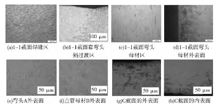
(a) Weld zone of section I-I (b) Transition zone of section I-I near the elbow
(c) Elbow parent material zone of section I-I (d) External surface of elbow parent material of section I-I
(e) External surface of elbow A (f) External surface of straight tube parent material
(g) External surface of section C (h) Internal surface of section C
Figure 2 Metallographic Observations of the Base Material
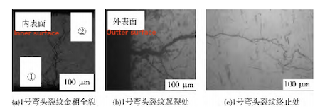
(a) Overall metallographic image of the crack on elbow No. 1 (b) The starting point of the crack on elbow No. 1
(c) The end point of the crack on elbow No. 1
Figure 3 Metallographic Observations of the Crack Section
4.2.1 Termination Point of the Crack in Elbow No. 1
A comparison between the crack section (Figure 3(b)) and the metallographic image of the elbow's base material surface in the weld ripple zone (Figure 2(b)) reveals the absence of slip lines in the weld ripple zone. This indicates that there is no work-hardened layer present in this area. Consequently, it can be inferred that the crack is located within the base material region of the elbow, rather than in the transition zone.
The localized increase in temperature during the welding process effectively serves as an annealing heat treatment for both the weld area and the adjacent weld ripple zone. This thermal exposure reduces the steel's hardness and eliminates the hardened layer on the surface of the base material in the weld ripple zone. Such annealing processes are known to relieve residual stresses and soften the material, thereby enhancing its ductility and reducing the likelihood of crack initiation in these areas.
5. Hardness Analysis of the Work-Hardened Layer
To confirm the presence of a work-hardened layer on the outer surface of the elbow's base material, micro Vickers hardness testing was conducted using a Wilson VH1102 tester. Hardness measurements were taken at approximately 20 µm from the outer surface, at the central area, and at the inner surface of Elbow No. 1. The test conditions included a 100 g load with a 15-second dwell time. The spacing between test points near the outer surface and the central area was approximately 0.2 mm, with 15 positions measured from left to right.
The comparison results of the near outer surface and central area hardness are shown in Table 3. The average hardness of the outer surface was 208.9 HV, while the average hardness of the central area was 158.7 HV. This indicates that the outer surface hardness is approximately 31.6% higher than that of the central area. These hardness results further confirm the presence of a work-hardened layer on the outer surface of the elbow, suggesting that the elbow manufacturing process involved cold working.
Table 3: Micro Vickers Hardness Measurements of Elbow No. 1 Base Material
Survey Area | Near Surface (HV) | Central Area (HV) |
1 | 195.2 | 154.6 |
2 | 246.8 | 153.8 |
3 | 224.6 | 166.0 |
4 | 189.8 | 151.2 |
5 | 197.9 | 155.4 |
6 | 190.2 | 166.4 |
Average | 208.9 | 158.7 |
6. Scanning Electron Microscopy and Energy Dispersive X-ray Spectroscopy Analysis
6.1 Scanning Electron Microscopy Analysis of Elbow No. 1
The crack cross-section in the 1-L region of Elbow No. 1 was examined using scanning electron microscopy (SEM), as depicted in Figures 4(a) to 4(b). The SEM images reveal the presence of precipitates along the crack propagation path, indicating partial corrosion or material degradation. Further SEM analysis of the outer surface of the crack in the 1-L region (Figure 4(c)) shows additional precipitates at specific locations, as highlighted in the enlarged view in Figure 4(d). These observations suggest that the crack initiation and propagation may be influenced by partial corrosion, potentially exacerbated by environmental factors such as chloride exposure.
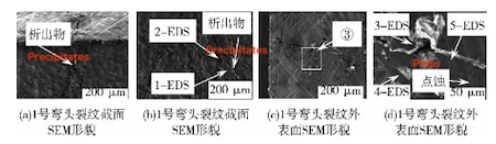
(a) SEM morphology of the crack cross section of elbow No. 1
(b) SEM morphology of the crack cross section of elbow No. 1
(c) SEM morphology of the outer surface of the crack of elbow No. 1
(d) SEM morphology of the outer surface of the crack of elbow No. 1
Figure 4: SEM Morphology of Elbow Crack
6.2 Scanning Electron Microscopy Analysis of Tee Surface
The surface of the tee was polished with sandpaper to remove corrosion products, and a characteristic area was sectioned for analysis. After ultrasonic cleaning with alcohol, the surface was examined using scanning electron microscopy (SEM). The SEM images revealed randomly distributed pits of varying sizes on the outer surface of the tee. These pits are likely caused by partial corrosive media. Considering the service environment of the SHY pipeline, it is inferred that salt deposition from the atmospheric environment led to the observed corrosion. The detected pits are shallow, with depths less than 0.1 mm, and are not expected to significantly impact the pipeline's integrity, given that the minimum wall thickness at the elbow's outer bend is 2.5 mm.
6.3 Energy Dispersive X-ray Spectroscopy Analysis of Elbow Crack Area
Energy dispersive X-ray spectroscopy (EDS) was performed on the crack area of Elbow No. 1, focusing on typical positions as shown in Figures 4(b) and 4(d). The analysis indicated that the chromium (Cr) content at positions 1 and 2 along the crack propagation path is significantly higher than that of the base material. These precipitates are identified as brittle Fe-Cr intermetallic compounds. The formation of such compounds can lead to chromium-depleted zones at grain boundaries, reducing the corrosion resistance of stainless steel and making these areas susceptible to pitting and stress corrosion cracking (SCC). Additionally, chlorine (Cl) elements were detected in the precipitates at positions 3 and 4 within the crack area and inside the pits, suggesting that vapor deposition occurred on the elbow's surface, contributing to pitting corrosion.
7. Comprehensive Analysis
Material Analysis: The cracked elbow submitted for inspection is composed of austenitic stainless steel (304L). Numerous slip lines are present on the outer surface of the elbow's base material. Hardness testing confirms the existence of a work-hardened layer on the outer surface, indicating that the elbow underwent cold working. Carbide precipitates are observed at the grain boundaries of the base material, and Fe-Cr metal compounds are identified along the crack propagation path. The presence of these precipitates suggests the formation of chromium-depleted zones at the grain boundaries, which compromise the protective nature of the oxide film. This compromised film is prone to rupture and exhibits low density, thereby diminishing the corrosion resistance of the stainless steel. The combination of the work-hardened layer and microstructural defects increases the material's susceptibility to stress corrosion cracking (SCC).
Environmental Analysis: Based on on-site environmental assessments of the pipeline, observations of pitting on the surfaces of the elbow and tee, and energy-dispersive spectroscopy (EDS) results, it is evident that the stainless steel elbow operates in a humid environment rich in gaseous ions.
Stress Analysis: The crack is located in the base material area adjacent to the weld, where residual stresses from welding are inevitable. These residual stresses can disrupt the integrity of the stainless steel's passivation film. Additionally, the elbow underwent cold working without subsequent heat treatment or with improper heat treatment, leading to residual stresses in the hardened outer layer. This hardening induces slip bands within the grains, causing partial stress concentrations that further compromise the passivation film and reduce corrosion resistance. Notably, under identical service conditions, numerous pits are observed on the surfaces of the tee and straight pipe, and residual welding stresses are present in their weld zones. However, these components did not exhibit through-wall leakage, indicating that while pitting and welding residual stresses contribute to degradation, the residual stresses in the hardened outer layer of the cold-worked elbow are the primary factors leading to pipeline failure.
Conclusion: The cracking of the stainless steel double-wall pipe's outer casing elbow is attributed to a combination of factors: Intrinsic material properties and microstructural defects that increase susceptibility to stress corrosion cracking (SCC), exposure to a humid environment rich in gaseous ions, and residual stresses in the base material near the weld and resulting from cold working processes. The interplay of these factors culminates in the stress corrosion cracking observed in the stainless steel double-wall pipe's outer casing elbow.
8. Conclusion
Macroscopic analysis, microstructural examination, and chemical composition testing confirm that the cracking in the stainless steel elbow of the hydrogen supply double-walled pipe originates in the base material near the weld. The identified failure mechanism is stress corrosion cracking (SCC).
The main contributing factors are:
· A work-hardened layer and precipitates at the grain boundaries of the elbow base material are present, which increase the material’s susceptibility to stress corrosion cracking (SCC).
· Residual stresses exist in the base material near the elbow weld, compounded by additional stresses introduced during cold working in the fabrication process.
· The elbow operates in a humid service environment with gas ion deposition, which promotes corrosive attack and contributes to SCC initiation.
The interaction of these three factors leads to the development of stress corrosion cracking in the stainless steel outer casing elbow.
To mitigate such failures, the following improvement measures are recommended:
·Straight pipes, elbows, and tees in the double-walled hydrogen supply system should be protected from direct exposure to gas ion-rich environments.
·Targeted remediation measures should be implemented to reduce humidity levels in the GB trench area.
·Regular inspections should be conducted on the elbows and tees in the pipeline system, and any components showing signs of defects must be replaced promptly.
·Factory acceptance protocols for elbows and tees should be enhanced to ensure full conformance to established quality standards.
Post URL: https://www.landeepipefitting.com/cracking-analysis-of-outer-casing-elbow-in-nuclear-hydrogen-pipes.html
Landee is a professional industrial pipe fitting manufacturer and be well accepted by customers all over the world, we has been producing Pipe Fitting for a variety of applications since 1985. welcome to access our website: https://www.landeepipefitting.com.
Next: Failure Analysis of Carbon Steel Elbow in Power Station Main Steam Pipe
