Abstract
During maintenance at a power plant, it was discovered that the hardness in the welded joint area of a P91 main steam elbow was low. During construction, it is necessary to remove the heat-affected zones (HAZ) at the elbow's inlet and outlet welds to prevent the effects of repeated high-temperature tempering on these zones. This requires replacing straight sections at the original positions of the elbow inlet and outlet. This paper investigates the impact of increasing the curvature radius of the pipe elbow as a solution to the issue associated with the HAZ of welded joints. By comparing the original elbow curvature radius with the increased radius in terms of construction feasibility, pressure loss, and stress analysis, it is found that increasing the curvature radius facilitates construction, reduces partial pressure losses, and does not adversely affect stress performance under high-parameter fluid conditions in large-diameter pipelines. Therefore, when replacement of a large-diameter pipe elbow is necessary, increasing the curvature radius is a viable solution.
Introduction
Pipes with outer diameters ranging from 325 mm to 1,200 mm and wall thicknesses between 10 mm and 200 mm are generally classified as large-diameter pipes. With the continuous advancement of industrial development, a growing number of large-diameter pipelines are being put into service. Over long-term operation, the microstructure of the heat-affected zone in these pipelines degrades, resulting in reduced tensile properties and an increased risk of fracture. To prevent such failures during operation, regular maintenance is carried out. This involves hardness testing of the base material, the heat-affected zone, and the welds at pipeline joints to assess the degree of aging and strength of each section’s microstructure. Based on the results, the safe service life of large-diameter pipelines can be reasonably estimated, and sections with insufficient hardness can be replaced in a timely manner.
1. Basic Information on Pipeline Elbows
The main steam pipeline of a boiler unit in a power plant has been in operation for over 100,000 hours. During maintenance, hardness tests were conducted on all stress concentration areas, including welds, elbows, and tees along the main steam pipeline. To ensure testing accuracy, the average value of five measurements taken at the same location was used. The results indicated an issue with one of the elbows. Specific data are provided in Table 1 and Figure 1. According to the standard DI/T 438-2023: Technical Supervision Regulations for Metals in Thermal Power Plants, the allowable hardness range for P91 pipe fittings is 180–250 HB. The measured hardness on the outer arc side and the weld joint area of the elbow fell below this standard, indicating the need for replacement. The elbow is made of P91 steel, with a 90° elbow, an inner diameter of 419 mm, a wall thickness of 75 mm, and a curvature radius of 870 mm. The working medium inside the pipe is water vapor. Under the boiler’s maximum continuous evaporation rate, the operating pressure is 25.48 MPa, the temperature is 571°C, and the steam flow rate is 1950 t/h.
Table 1. Elbow Hardness Test Results (HB)
Test Point | Hardness (HB) | Test Point | Hardness (HB) |
1 | 173 | 7 | 167 |
2 | 176 | 8 | 171 |
3 | 177 | 9 | 178 |
4 | 175 | 10 | 176 |
5 | 160 | 11 | 174 |
6 | 163 | 12 | 179 |
Standard Requirement (DL/T 438-2023): 180–250 HB | |||
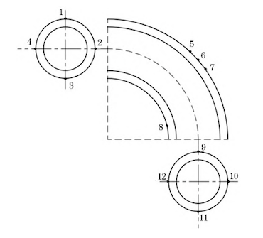
Figure 1 Hardness test of elbows
2. Treatment Method
Since the hardness of various areas of the P91 pipe elbow is lower than 180 HB, and the pipeline has been in operation for more than 100,000 hours, it is determined that its high-temperature tensile performance has degraded. Continued operation under these conditions may lead to cracking in the weld area, posing a risk to personnel and equipment safety. Therefore, elbows exhibiting similar issues must be replaced. P91 large-diameter pipelines require heat treatment after welding. To ensure construction quality, the heat-affected zone (HAZ) of the original welded joints must also be removed and replaced. This is because after the first tempering treatment following the initial welding of the P91 pipeline, the high-temperature tensile strength of the HAZ is at its peak. However, as the number of tempering cycles increases, the mechanical properties gradually decline.
If the HAZ of the original weld is retained, it will experience the highest temperature during the new welding process. The heat generated during welding directly affects the existing HAZ, effectively subjecting it to a second tempering. Following this, a third tempering occurs during post-weld heat treatment. As a result, the HAZ of the original weld undergoes three tempering cycles, significantly reducing its high-temperature tensile strength and increasing the risk of cracking during operation, thereby compromising pipeline safety. To ensure construction quality and eliminate the influence of the original weld HAZ, two construction plans are currently proposed:
Plan 1:
Replace the elbow with one of the same size and additionally install a 1-meter-long straight pipe section at both the inlet and outlet of the elbow. According to DL/T 869-2021 – Welding Technical Regulations for Thermal Power Plants, when the nominal diameter of the pipeline exceeds 500 mm, the distance between two butt welds must be no less than 500 mm. This plan requires a total of four welds.
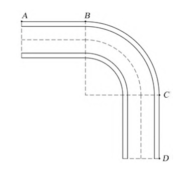
Figure 2 Construction with Original-Sized Elbow
Plan 2:
Replace the elbow with a new elbow of the same inner diameter and wall thickness, but increase the curvature radius to 914 mm. This eliminates the need for two additional straight pipe sections while also removing the influence of the original weld HAZ. This plan requires only two welds.
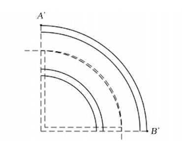
Figure 3 Construction with Increased Curvature Radius Elbow
3. Impact Analysis
The impact of increasing the curvature radius of the pipeline elbow is evaluated by comparing the construction processes outlined in Scheme 1 and Scheme 2, along with the associated local losses and stress conditions after replacement.
3.1 Construction Analysis
According to Scheme 1 (replacement based on the original elbow curvature radius), a total of four welds are required, as shown in Figure 2. During construction, the existing pipe is first cut at points A and D. Two new straight pipe sections (AB and CD) and a new elbow (BC) are then hoisted and fixed in position. Welding is carried out at the joints between A and B, B and C, C and D, and the overall construction period is approximately 12 days. In contrast, Scheme 2 (replacement using an elbow with a larger curvature radius) requires only two welds, as shown in Figure 3. In this approach, the existing pipe is cut at points A′ and B′. The new elbow (A′B′) is then hoisted and secured in place, and welding is performed at both ends. The total construction period is approximately 7 days.
It is evident that the construction period for replacing the elbow with a larger curvature radius is shorter than that of the original-sized elbow. This is primarily due to the reduction of two welds, which saves time and simplifies the process. Since only one elbow is replaced in Scheme 2, the installation and alignment of the component are more straightforward and efficient.
3.2 Local loss Analysis
As shown in Figure 4, when fluid flows through a 90° elbow, the pressure on the outer arc of the elbow is higher, while the pressure on the inner arc is lower. The maximum pressure differential occurs along the 45° section. Before entering the elbow, the pressure distribution in the pipe is uniform. As the fluid enters the 90° elbow, the pressure on the outer arc increases gradually from point a to point b, where it reaches its peak. Thereafter, the pressure decreases from point b to point c. On the inner arc, the pressure rises gradually from point d to point e. Due to the pressure variation across these sections (a–c and d–e), boundary layer separation occurs, forming vortices that contribute to partial energy loss.
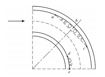
Figure 4 Fluid Flow in a 90° Elbow
The partial head loss due to flow through the elbow can be calculated using Equation (1):
Equation (1)
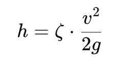
Where:
h is the local head loss (m);
ζ is the dimensionless local loss coefficient;
v is the flow velocity in the pipe (m/s);
g is gravitational acceleration, taken as 9.80 m/s².
According to principles of engineering fluid mechanics, the local loss coefficient for a 90° elbow can be determined using Equation (2):
Equation (2)
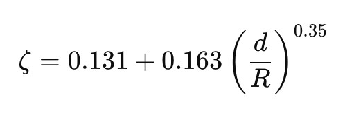
Where:
d is the inner diameter of the 90° elbow (mm);
R is the curvature radius of the elbow (m).
The pressure drop caused by local losses is calculated using Equation (3):
Equation (3)
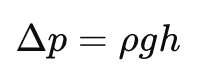
Where:
Δp is the pressure drop due to local loss (Pa);
ρ is the fluid density in the operating state (kg/m³).
In this case, the fluid medium is water vapor. Under the boiler’s maximum continuous evaporation condition, the operating pressure is 25.48 MPa, the temperature is 571 °C, and the steam flow rate is 1950 t/h. By substituting the elbow parameters from Construction Scheme 1 and Scheme 2 into Equations (1) through (3), the data shown in Table 2 are obtained.
Table 2. local loss Analysis for Different Elbow Curvature Radii
Parameter | Scheme 1 | Scheme 2 |
Elbow inner diameter, d (mm) | 419.000 | 419.000 |
Elbow curvature radius, R (mm) | 870.000 | 914.000 |
Fluid velocity in the elbow (m/s) | 0.970 | 0.970 |
Fluid density under current flow conditions, ρ (kg/m³) | 76.920 | 76.920 |
Dimensionless local loss coefficient, ζ | 0.144 | 0.142 |
Local head loss, h (mm) | 6.913 | 6.817 |
Pressure drop due to local loss, Δp (Pa) | 5.211 | 5.139 |
According to the calculation results, increasing the curvature radius of the pipe elbow reduces the local loss at the elbow.
3.3 Force Analysis
As shown in Figure 5, the force exerted by the fluid flow on a 90° elbow causes the elbow to react with an equal and opposite force to maintain equilibrium. Let the reaction force exerted by the elbow on the fluid be denoted as F, with its components along the x-, y-, and z-axes represented by Fx, Fy, and Fz, respectively.
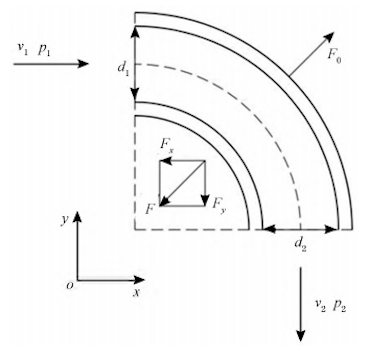
Figure 5 Stress conditions on a 90° elbow
The force exerted by the elbow at the inlet can be calculated using Equation (4):
Equation (4):
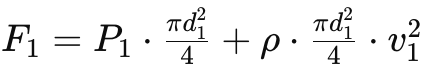
Where:
d1 is the inner diameter at the elbow inlet (m);
P1 is the fluid pressure at the elbow inlet (Pa);
v1 is the fluid velocity at the elbow inlet (m/s);
ρ is the fluid density (kg/m³);
π is taken as 3.1416.
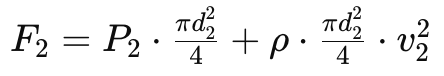
The equilibrium equation in the y-direction is given by Equation (5):
Equation (5):
Where:
d2 is the inner diameter at the elbow outlet (m);
P2 is the fluid pressure at the elbow outlet (Pa);
v2 is the fluid velocity at the elbow outlet (m/s).
Since the 90° elbow is symmetrically arranged about the xy-plane, the flow inside the elbow is also symmetric about this plane. As a result, the z-direction components of the forces cancel each other out, and all components of Fz are zero.
The net force F acting on the fluid is the vector sum of F1 and F2, and the reaction force of the elbow on the fluid is equal in magnitude and opposite in direction. The total force acting on the elbow can be calculated using Equation (6):
Equation (6):
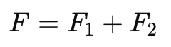
In this analysis, the medium in the pipeline is water vapor. Under the maximum continuous evaporation operating condition of the boiler, the working pressure is 25.48 MPa, the temperature is 571 °C, and the steam flow rate is 1950 t/h. Since the pressure drop caused by local losses in the elbow is relatively small, the outlet pressure is not significantly affected compared to the working pressure in the pipeline. By substituting the elbow parameters from Construction Schemes 1 and 2 into Equations (4) to (6), the results presented in Table 3 are obtained.
Table 3. Stress Analysis of Different Pipe Elbow Curvature Radii
Fitting Parameters | Scheme 1 | Scheme 2 |
Elbow curvature radius R (mm) | 870.000 | 914.000 |
Elbow inlet diameter d₁ (m) | 0.419 | 0.419 |
Elbow outlet diameter d₂ (m) | 0.419 | 0.419 |
Elbow inlet fluid pressure P₁ (MPa) | 25.480 | 25.480 |
Elbow outlet fluid pressure P₂ (MPa) | 25.480 | 25.480 |
Elbow inlet fluid flow rate v₁ (m/s) | 0.970 | 0.970 |
Elbow outlet fluid flow rate v₂ (m/s) | 0.970 | 0.970 |
Fluid density ρ (kg/m³) | 76.920 | 76.920 |
x-direction force Fₓ (N) | 3,513,335.000 | 3,513,335.000 |
y-direction component force Fᵧ (N) | 3,513,335.000 | 3,513,335.000 |
Total force on 90° elbow F (N) | 4,968,606.000 | 4,968,606.000 |
According to the calculation results, when the working pressure of the medium in the pipeline is sufficiently high, the pressure loss at the elbow can be considered negligible. In this case, increasing the curvature radius of the pipeline elbow does not affect the stress on the elbow under the same fluid parameters. However, based on the formula analysis, the greater the pressure drop caused by local loss, the lower the fluid pressure at the elbow outlet, and consequently, the lower the force acting on the elbow—and vice versa.
4. Conclusion
- Under the same medium conditions, if the inner diameter of the 90° elbow remains unchanged, increasing the curvature radius reduces the local loss at the elbow.
- When the working pressure of the medium in the pipeline is high and the local loss at the elbow can be neglected, changes in the curvature radius do not affect the force acting on the elbow, provided the inner diameter remains constant.
- When a large-diameter pipeline elbow deteriorates and requires replacement, it is essential not only to cut and replace the elbow from its base, but also to account for the heat-affected zone (HAZ) of the original welded joint. To avoid repeated tempering of the original HAZ, the affected section must also be removed.
Taking the example of high-pressure pipe fittings with a 90° bend, an inner diameter of 419 mm, and a wall thickness of 75 mm used in a power plant’s main steam pipeline: replacing the elbow with one of a larger curvature radius enables removal of the original welded HAZ and shortens the construction period. Compared with the original-radius elbow, this solution slightly reduces local loss while keeping the overall stress on the elbow unchanged.
Post URL: https://www.landeepipefitting.com/impact-of-curvature-radius-changes-on-large-diameter-pipe-elbow-performance-and-maintenance.html
Landee is a professional industrial pipe fitting manufacturer and be well accepted by customers all over the world, we has been producing Pipe Fitting for a variety of applications since 1985. welcome to access our website: https://www.landeepipefitting.com.
Next: Cracking Analysis of Outer Casing Elbow in Nuclear Hydrogen Pipes
