Abstract
To investigate the leakage issue at the elbow section of the surge pipe located in the top cover of a large hydropower station, PT (penetrant testing) was conducted on the weld seams, along with physical and chemical analysis of the base material. The findings revealed that the immediate cause of the elbow failure was the presence of cracks in both the weld seam and the heat-affected zone (HAZ) of the base material. These results provide a useful reference for analyzing similar leakage issues in turbine surge pipes.
The surge pipe installed in the turbine’s top cover serves to manage leakage from the turbine’s sealing ring during generator operation. Its safe and stable performance is critical to the integrity of the top cover and the turbine runner. Weld seam leakage in the top cover surge pipe is a common defect, often caused by multiple and complex factors, and poses significant risk. Severe leakage may result in internal flooding, misdirection of water, or even inundation of the power plant. Therefore, ensuring the reliable operation of the surge pipe in the top cover is of vital importance.
The vertical shaft mixed-flow turbine of a large hydropower station has a rated head of 197 meters and a rated output of 784 MW. The turbine’s top cover adopts a welded steel plate structure, which primarily serves to guide and support the guide vane bearing and its operating mechanism. It also houses and secures the leak-proof ring, supports the water guide bearing and main shaft seal, and accommodates the cooling system for the water guide bearing, as well as the pipeline system and main oil tank for the main shaft seal.
Eight surge pipes are arranged radially inside the top cover. These pipes are made of 06Cr19Ni10 stainless steel and adopt a three-section welded structure, as illustrated in Figure 1. The pipe has an outer diameter of 325 mm and a wall thickness of 13 mm. One end of each surge pipe connects to a pressure relief hole on the runner crown, while the other end is connected to the turbine’s tailwater pipe via a buried pipe.
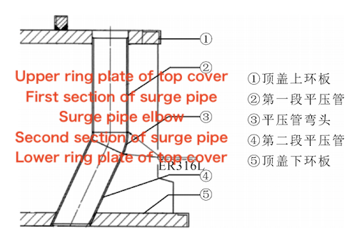
Figure 1 Structural diagram of the surge pipe inside the top cover of a hydropower station
During the annual maintenance of one unit, leakage was detected at the No. 2 surge pipe elbow, which is located between the upper and lower ring plates of the top cover, during the tailwater filling stage of the inspection. Upon replacing this elbow section, a crack was discovered in the elbow body. Subsequent inspections revealed water seepage at the No. 1, 3, and 5 surge pipe elbows, where surface cracks were also observed. Slight rust was noted on the weld seams of the other surge pipe elbows.
Failure analysis was carried out on the elbows of surge pipes No. 1 and No. 5. Visual inspection revealed the presence of cracks on both the inner and outer surfaces. For clarity in the subsequent analysis, the welds on either side of the elbows are designated as follows: "Weld seam No. 1-A" and "Weld seam No. 1-B" for the No. 1 surge pipe elbow, and "Weld seam No. 5-A" and "Weld seam No. 5-B" for the No. 5 surge pipe elbow.
1. PT Flaw Detection at the Surge Pipe Weld Seam
Before dissection, the weld seam areas and adjacent surfaces on the inner and outer sides of the surge pipe elbows in the No. 1 and No. 5 top covers were polished to remove paint. PT flaw detection was then carried out. The PT flaw detection results are shown in Figure 2. Multiple cracks were found on the inner and outer surfaces of weld seams A and B of the No. 1 and No. 5 elbows, located near the weld seam fusion line. The cracks ranged in length from 15 mm to 400 mm. The cracks on the inner surface were significantly longer than those on the outer surface. Incomplete welding and misalignment defects were also observed on the inner surface of the weld seam. Cracks were found at the fusion line and in the parent material on the outer surface weld seam of the No. 1 and No. 5 elbows. Based on these findings, it can be intuitively concluded that the leakage at the surge pipe elbows was caused by cracks.
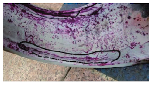
Figure 2: PT flaw detection of the inner and outer weld seam surfaces of the surge pipe elbows in the top cover
2. Physical and Chemical Inspection and Analysis of the Surge Pipe Parent Material
2.1 Chemical Composition Inspection
A sample was taken from the body of the elbow's parent material, and its chemical composition was tested using a direct-reading spectrometer. The test results are shown in Table 1. The parent material complies with the chemical composition requirements for 06Cr19Ni10 specified in GB/T 14976-2012.
Table 1 Chemical Composition Test Results (wt%)
Element | C | Si | Mn | P | S | Cr | Ni | Cu |
No. 1 Measured Value | 0.052 | 0.49 | 1.60 | 0.033 | 0.0008 | 17.85 | 7.99 | 0.15 |
No. 5 Measured Value | 0.056 | 0.50 | 1.61 | 0.035 | 0.008 | 18.00 | 7.94 | 0.15 |
Required Value (06Cr19Ni10) | ≤0.08 | ≤1.00 | ≤2.00 | ≤0.035 | ≤0.030 | 18.00–20.00 | 8.00–11.00 | - |
Permissible Deviation | ±0.01 | ±0.05 | ±0.04 | +0.005 | +0.005 | ±0.20 | ±0.10 | - |
2.2 Mechanical Properties Test
Two tensile specimens and one hardness specimen were taken from the base metal of the No. 1 and No. 5 elbows, respectively. The test results are presented in Table 2. One tensile specimen from the No. 1 elbow did not meet the technical requirements. Although the tensile properties of the other specimens met the required standards, numerous small cracks were visible to the naked eye on the surface of the tensile specimens.
2.3 Metallographic Structure Test
Samples were taken from the weld joint and the base metal. After rough grinding, fine grinding, and polishing, aqua regia etching was applied, and the metallographic structure was observed under a metallographic microscope.
In the weld seams of the No. 1 and No. 5 elbows, columnar crystals were observed near the fusion line, with dendritic and equiaxed crystals in the center of the weld seam. The structure was identified as austenitic. The heat-affected zone (HAZ) exhibited coarse austenite with visible grain separation and intergranular cracks. Along the weld toe in the elbow's HAZ, distinct stress corrosion cracks extending along the grain boundaries were observed, while the base metal showed an austenitic structure.
Point-like precipitates were present at the grain boundaries of the base metal in the No. 1 elbow. Additionally, significant stress corrosion cracks extending along the grain boundaries were observed near the inner surface of the base metal in the No. 5 elbow, as shown in Figure 3.
Table 2 Mechanical Properties Test Results
Specimen | Yield Strength Rp₀.₂ (MPa) | Tensile Strength Rₘ (MPa) | Elongation A (%) | Hardness HBW |
No. 1 – Sample 1 | 329 | 637 | 7.5 | 184 |
No. 1 – Sample 2 | 349 | 674 | 28.0 | 179 |
No. 5 – Sample 1 | 298 | 677 | 51.5 | — |
No. 5 – Sample 2 | 295 | — | 58.0 | — |
Requirement | ≥ 205 | ≥ 520 | ≥ 35 | ≤ 190 |
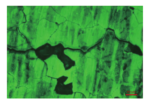
Figure 3 Metallographic structure of No. 5 elbow weld joint and base material
2.4 Intergranular Corrosion Test
Samples were taken from the elbow’s base material, and intergranular corrosion tests were carried out in accordance with GB/T 4334.101. The sample surfaces were polished and then electrolytically etched in a 10% oxalic acid solution. The etched surface was examined under a metallographic microscope. Corrosion grooves were observed along the grain boundaries, and some or all grains were surrounded by these grooves. After bending the samples, visible cracks appeared on the reverse sides and flanks of elbows No. 1 and No. 5. The intergranular corrosion test results were deemed non-compliant.
2.5 Macro and Micro Fracture Analysis
2.5.1 Macroscopic Fracture Analysis of Elbows
Samples were taken from No. 1 weld seam and No. 5 weld seam. The fracture surfaces after ultrasonic cleaning are shown in Figure 4. The fracture surfaces appeared dark, with rust marks visible near the outer circumference. The fractures were oblique and uneven, with crack propagation directions approximately parallel to the weld seam's heat-affected zone. The final fracture zone was located near the outer circumference, and incomplete fusion was observed at the weld seam near the inner circumference. Based on these observations and the metallographic analysis, it is determined that due to geometric stress concentration at the weld root and brittle stress concentration at the weld toe, the crack originated at the weld toe and propagated along the heat-affected zone toward the outer circumference, ultimately resulting in failure. The fracture type is preliminarily identified as brittle fracture caused by stress corrosion cracking.
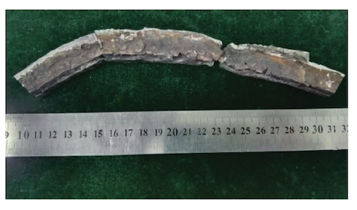
Figure 4 Macroscopic fracture morphology of elbow No. 1
2.5.2 Microscopic Fracture Analysis of Elbow
Energy spectrum analysis was performed on the attachments at the cracks on the fracture surface. As shown in Figure 5 and Table 3, compared to the parent material, the attachments contained excessive amounts of elements such as O, C, Ca, and Si. It is speculated that these elements may be residues produced after the mud slurry containing CaCO₃, CaSiO, or SiO₂ interacted with the elbow body.
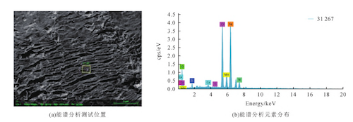
(b) Energy Spectrum Analysis Element Distribution (a) Energy Spectrum Analysis Test Position
Figure 5: Energy Spectrum Analysis Test Position and Element Distribution of Elbow No. 1
Table 3: Energy Spectrum Analysis Results of Elbow No. 1
Element | Weight Percentage (wt%) |
C | 19.67 |
O | 32.67 |
Si | 2.28 |
Ca | 0.70 |
Ti | 0.04 |
Cr | 15.78 |
Mn | 1.29 |
Fe | 24.35 |
Ni | 3.22 |
The microscopic fracture morphology of the elbow was analyzed using scanning electron microscopy. As shown in Figure 6, crack-like attachments are visible on the fracture surface, with rock candy-like patterns observed in certain areas. Based on the results of the microscopic fracture morphology analysis, it can be concluded that the fracture morphology of the elbow exhibits the characteristic features of stress corrosion cracking.
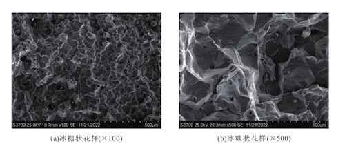
(a) Rock candy-like pattern (×100) (b) Rock candy-like pattern (×500)
Figure 6: Microscopic Fracture Morphology of Weld Seam No. 5-A
3. Conclusion
The failure analysis of the flat-pressure pipe elbow at the power station revealed that the direct cause of the failure was the presence of cracks in both the weld seam and the heat-affected zone, assuming the parent material met the required standards. The main contributing factors to the formation of these cracks are as follows:
- The welding process did not meet the required standards, resulting in incomplete weld penetration, which led to substandard intergranular corrosion resistance and stress corrosion resistance of the elbow’s parent material.
- The elbow weld seam was exposed to river water containing mud slurry impurities over an extended period, causing intergranular corrosion cracking and a reduction in material toughness.
- Geometric stress concentration occurred at the inner circle of the elbow, and residual welding stress contributed to crack formation at the weld toe at the root of the inner surface. These cracks propagated along the heat-affected zone, eventually leading to failure.
This analysis provides valuable insights that may help address similar turbine surge tank failure issues in the future.
Post URL: https://www.landeepipefitting.com/failure-analysis-of-surge-pipe-elbow-in-the-top-cover-of-a-large-hydropower-station.html
Landee is a professional industrial pipe fitting manufacturer and be well accepted by customers all over the world, we has been producing Pipe Fitting for a variety of applications since 1985. welcome to access our website: https://www.landeepipefitting.com.
Next: Impact of Curvature Radius Changes on Large-Diameter Pipe Elbow Performance and Maintenance
