Abstract: A leakage occurred in the elbow section of the sampling pipeline connected to the liquid level gauge of a high-temperature reheat steam drain tank in a thermal power plant during normal operation. The root cause of the elbow failure was investigated using macroscopic observation, chemical composition analysis, metallographic examination, hardness testing, and other diagnostic methods. The results indicate that the elbow experienced stress corrosion cracking (SCC), primarily caused by improper heat treatment during manufacturing and water accumulation along the lower inner wall, which created a localized corrosive environment. These factors collectively led to crack initiation and eventual leakage. Cracking and leakage in steam-water pipelines outside the boiler pose a significant threat to the safe and stable operation of thermal power units and may result in equipment damage or even personal injury. Therefore, the operating conditions of such high-temperature, high-pressure pipelines must be closely monitored and strictly managed to prevent failures and ensure long-term reliability and safe operation.
A leakage occurred in the sampling pipeline of the liquid level gauge in the high-temperature reheat steam drain tank of Unit 1 at a thermal power plant after 168 hours of trial operation (see Figure 1). The pipeline is horizontally oriented and consists of two branches—an upper and a lower line—extending from the reheat steam drain tank to the liquid level gauge. The leakage point was located at the lower section of a bent (elbow) pipe between the bottom of the reheat steam drain tank and the inlet of the primary isolation valve. The leaking pipe section was designed with a specification of 28 mm × 4 mm (outer diameter × wall thickness) and was made from SA-213 T91 alloy steel. The pipeline operates at a pressure of 3.5 MPa and a temperature of 568 °C. To identify the root cause of the leakage and prevent similar incidents, the failure was investigated through a series of physical and chemical testing methods.
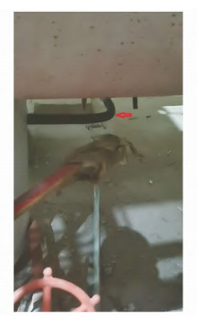
Figure 1. Macroscopic appearance of the leaking section of the pipeline
1. Physical and Chemical Testing
1.1 Macroscopic Observation
Following shutdown, inspection revealed that the leakage was located at the 6 o’clock position on the longitudinal section of the elbow pipe. The axial location of the leak along the elbow is illustrated in Figure 2. After cutting the pipe, a penetration test was performed, revealing two linear defects circumferentially distributed around the leakage area. These defects measured approximately 3 mm and 2 mm in length, respectively (see Figure 3). After light surface grinding, it was confirmed that the defects were not machining-related issues, such as scratches, linear marks, or material folds. Based on a comprehensive assessment, the defects were identified as cracks. Further measurements confirmed that the elbow’s wall thickness, out-of-roundness, waviness, and straight section length all met the specifications outlined in DL/T 515–2018: Power Station Elbow. Operational records from the 168-hour trial run were reviewed, revealing no abnormal conditions such as overtemperature or overpressure. Based on these findings, external mechanical damage and short-term overheating can be reasonably ruled out as causes of the elbow leakage.
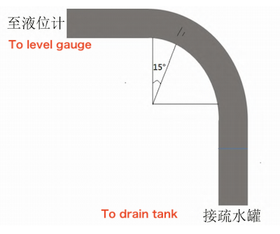
Figure 2. Axial location of the leakage point in the elbow pipe

Figure 3. Penetration test results revealing linear surface defects around the leakage area
1.2 Chemical Composition Analysis
In accordance with DL/T 991-2006, Technical Guidelines for Metal Spectroscopic Analysis of Power Equipment, the chemical composition of the elbow was determined using an ARL 3460 direct-reading spectrometer. The results are presented in Table 1. As shown, the measured chemical composition of the elbow meets the requirements of ASME SA-213/SA-213M-2017, “Seamless Ferritic and Austenitic Alloy Steel Boiler, Superheater, and Heat Exchanger Tubes.”
Table 1. Chemical Composition Analysis Results of the Elbow (unit: %)
|
Element |
C |
Si |
Mn |
S |
Cr |
Mo |
V |
Nb |
|
Measured |
0.11 |
0.36 |
0.45 |
0.007 |
8.32 |
1.01 |
0.21 |
0.06 |
|
Standard |
0.08–0.12 |
0.20–0.50 |
0.30–0.60 |
≤0.010 |
8.00–9.50 |
0.85–1.05 |
0.18–0.25 |
0.06-0.1 |
1.3 Metallographic Inspection
A metallographic sample was taken by sectioning the elbow along its axial direction. The sampling location is shown in Figure 4. In accordance with DL/T 884-2019, Technical Guidelines for Metallographic Inspection and Evaluation of Thermal Power Plants, the sample was examined using a ZEISS Observer A1m optical microscope. The polished morphology of the crack at Position 1 is shown in Figure 5. Two primary cracks are visible at this location, along with several secondary (auxiliary) cracks extending vertically from the inner wall toward the outer wall. The auxiliary cracks range in length from 200 to 900 μm. All observed cracks exhibit a serrated morphology with no significant bifurcation. No additional cracks or microcracks were found on the tube’s outer wall, indicating that the principal stress direction is axial. The microstructure near the crack at Position 1 is shown in Figure 6. The crack displays a mixed fracture morphology, combining both transgranular and intergranular features, with visible oxidation and corrosion products present inside the crack. The surrounding microstructure consists of fine-grained martensite. Due to the small grain size, the martensite orientation is indistinct. The measured grain size corresponds to ASTM grain size grade 11.5. The microstructure at Position 2 is shown in Figure 7. No microcracks or signs of mechanical processing damage were observed on the inner wall. The microstructure also consists of fine-grained martensite, with a grain size corresponding to grade 11.

Figure 4. Schematic diagram showing the metallographic sampling location
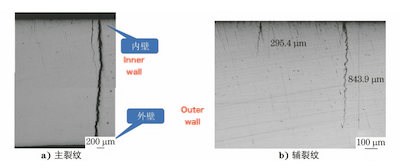
a) Main crack b) Secondary crack
Figure 5. Polished surface morphology of the crack at Position 1

Figure 6. Microstructure at the crack site in Position 1

a) Polished state b) Corroded state
Figure 7. Microstructure observed at Position 2
1.4 Hardness Test
Hardness measurements were performed on samples taken from Positions 1 and 2 of the elbow. Testing was carried out using a universal hardness tester in accordance with GB/T 231.1-2018, Metallic Materials—Brinell Hardness Test—Part 1: Test Method. The results are presented in Table 2. As shown, the measured Brinell hardness (HBW) values significantly exceed the specified technical requirements, indicating that the elbow hardness does not meet product specifications. This excessive hardness may have contributed to crack initiation and eventual failure.
Table 2. Brinell Hardness Test Results at Positions 1 and 2 (Unit: HBW)
|
Item |
Position 1 (Crack Area) |
Position 1 (Back) |
Position 2 |
|
Measured Value |
366 |
364 |
363 |
|
Technical Requirement |
190–250 |
190–250 |
190–250 |
2. Comprehensive Analysis
2.1 Causes of High Hardness in the Bent Pipe
According to product specifications, the normalizing temperature during the heat treatment of T91 steel pipes must be at least 1040°C, and the tempering temperature must not be lower than 730°C. After normalizing, a T91 steel pipe with dimensions of 42 mm × 5 mm (outer diameter × wall thickness) typically develops a fine-grained, uniform low-carbon martensitic microstructure with a hardness of approximately 385 HBW. Following high-temperature tempering, the microstructure transforms, resulting in reduced hardness and enhanced ductility. However, the measured hardness of the cracked bent pipe closely matched that of the normalized-only condition, indicating that the pipe either did not undergo high-temperature tempering during manufacturing or that the tempering process parameters did not meet required standards.
2.2 Causes of Cracking
2.2.1 Types of Cracks
Cracks in metal components are generally classified into two categories based on their origin: process-induced cracks and service-induced cracks. Process-induced cracks develop during manufacturing processes such as casting, forging, welding, or grinding, with common examples including casting cracks and grinding cracks. Service-induced cracks develop during operation and include mechanical stress cracks, fatigue cracks, stress corrosion cracking, and creep cracks. In this case, the cracks were located outside the weld’s heat-affected zone (HAZ), effectively ruling out welding cracks as the cause. Additionally, no processing defects—such as straight lines, pits, or surface indentations—were observed near the crack origin on the pipe’s inner wall, ruling out machining-induced cracking. Although surface network cracks can develop due to improper heat treatment, this possibility is inconsistent with the observed crack morphology in the elbow. Cracks or fractures caused by bending stress typically occur on the outer arc of the elbow during forming; however, the detected crack was located along the neutral axis, which contradicts this mechanism. In terms of mechanical stress, the maximum stress typically occurs on the outer arc of the elbow, particularly at the 45° section, where the wall thickness is thinnest and stress concentration is highest. However, since the crack initiation point is not located within this high-stress zone, mechanical overstress cracking can be ruled out. If the elbow were subjected to alternating thermal stress, thermal fatigue cracks could develop, typically initiating at the water-steam interface. These cracks generally display a characteristic fracture surface, consisting of a smooth fatigue zone followed by a rough final fracture zone. However, the crack in this case is located directly beneath the pipe, and its fracture morphology does not correspond to typical thermal fatigue cracking, thereby ruling out fatigue failure. Moreover, the pipeline had a short operational lifespan, and no microstructural evidence of creep damage was detected, ruling out creep cracks as a potential failure mechanism.
2.2.2 Formation Mechanism of Stress Corrosion Cracking
Stress corrosion cracking (SCC) refers to the delayed fracture of metal materials caused by the combined effects of tensile stress and exposure to a specific corrosive environment. During operation, the elbow was primarily subjected to axial tensile stress, compounded by residual stresses introduced during manufacturing and bending processes. Studies have shown that residual stresses generated by cold and hot working processes are key contributors to stress corrosion cracking (SCC). In this case, residual stresses were introduced during both hot rolling and normalizing of the pipe and were not effectively relieved because the original elbow pipe either did not undergo high-temperature tempering or was insufficiently tempered. Additionally, before field installation, the elbow was formed by cold bending a straight pipe. According to DL/T 515-2018 — Power Station Elbow, when the strain rate ranges from 5% to 25% and the bending radius is between 56 mm and 280 mm, stress-relief heat treatment is mandatory. The measured bending radius of the elbow was approximately 108 mm; however, no stress-relief heat treatment was performed during on-site construction. Consequently, significant residual stresses remained in the bent section. Higher residual stress increases the likelihood of cracking. Stress corrosion typically causes brittle fracture. In this case, the fracture occurred nearly perpendicular to the pipe’s outer wall, exhibiting classic characteristics of brittle failure. Stress corrosion cracking (SCC) occurs only when a specific alloy is exposed to a particular corrosive environment. P91 steel (equivalent to T91), a high-alloy, high-strength ferritic steel, is known to be susceptible to cracking in media such as distilled water and chloride-containing solutions. After installation, the elbow was insulated and put into service with minimal drying time. While the outer wall remained mostly dry and free from corrosive exposure, the inner wall—particularly the lower section of the horizontally oriented elbow—was prone to water accumulation during startup, operation, and shutdown. This resulted in localized corrosive conditions. The gray coloration of the fracture surface, along with the presence of corrosion products, further supports the diagnosis of stress corrosion cracking (SCC). In conclusion, the elbow failure was caused by SCC.
2.2.3 Types of Stress Corrosion Cracking
From an electrochemical perspective, stress corrosion cracking (SCC) can be classified into two types:
Anodic Pathway Cracking (APC): Results from anodic dissolution.
Hydrogen Embrittlement Cracking (HEC): Caused by infiltration of hydrogen atoms.
Low-alloy, high-strength steels such as P91/T91 are particularly susceptible to hydrogen embrittlement cracking (HEC)-type stress corrosion cracking. This mechanism involves a hydrogen evolution reaction occurring at the cathodic sites on the metal surface. Hydrogen atoms permeate the metal lattice, particularly under sustained tensile stress. As microcracks initiate, stress concentration at the crack tips encourages further hydrogen accumulation, accelerating crack propagation and ultimately leading to fracture. In this case, no significant corrosion marks were observed on the inner wall of the elbow, and the brittle fracture occurred perpendicular to the wall surface—both consistent with the characteristics of hydrogen-induced embrittlement. Therefore, the elbow failure is identified as hydrogen embrittlement cracking (HEC)-type stress corrosion cracking.
3. Conclusions and Recommendations
The cracks in the elbow were identified as stress corrosion cracking (SCC) caused by cathodic hydrogen embrittlement (HEC). The elbow did not undergo high-temperature tempering during manufacturing, nor was stress-relief heat treatment applied after cold bending. Additionally, water accumulation on the lower inner wall of the elbow created a corrosive environment, which was the primary cause of cracking and leakage. It is recommended to replace all elbows of the same type within the unit and to perform stress-relief heat treatment after cold bending during manufacturing to prevent similar failures in the future.
Post URL: https://www.landeepipefitting.com/elbow-crack-and-leakage-in-a-high-temperature-reheat-steam-drain-tank-sampling-pipeline.html
Landee is a professional industrial pipe fitting manufacturer and be well accepted by customers all over the world, we has been producing Pipe Fitting for a variety of applications since 1985. welcome to access our website: https://www.landeepipefitting.com.
Next: Pipe Cap Hot-Forming: Heating Temperature and Blank Size Study
