Failure Analysis of the Cracking of Stainless Steel Tees in Industrial Pipelines (Part One)
Posted: 04/27/2021 09:22:08 Hits: 44
Abstract: An austenitic stainless steel tee in an industrial pipeline of a coal chemical plant cracked and failed in the use process. Inspection and sampling tests are performed for the tee in this article, including macroscopic inspection, hardness measurement, metallographic analysis and scanning electron microscopy, and the failure causes were analyzed in detail. The results showed that the tee was cracked due to corrosion fatigue of the material, and targeted suggestions were given finally.
1. Overview
A stainless steel tee in an acid water industrial pipeline of a coal chemical plant cracked and failed. The operating pressure of the pipeline is 0.6MPa; the operating temperature is between 60 and 70℃; the medium is acid water. The material of the cracked tee is 0Cr18Ni9 (SH3408-96) with a specification of 89mm × 4.0mm.
2. Inspection
2.1 Macro inspection
A macro inspection of the tee showed that there was no obvious pitting or other thinning caused by corrosion in any area. The crack position is located in the middle of the tee, which is a bit away from the welding seam area. The crack is big; the width of the opening is wide, and the cracks are straight and have a few branches. There are multiple cracks on the front of the tee, and the crack at the back is a single crack. There was no obvious deformation except for the crack tip at the back. See Figure 1 and Figure 2.
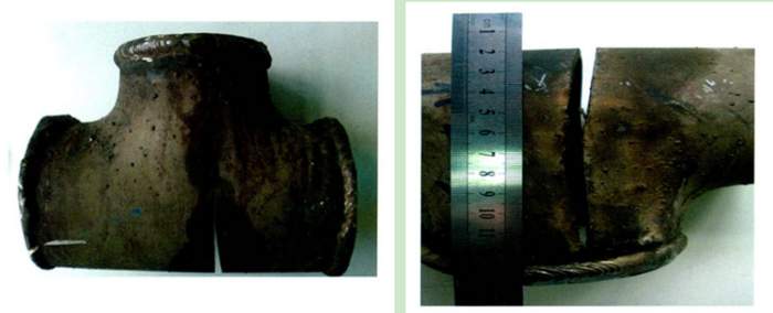
Figure 1 The front of the cracked stainless steel tee Figure 2 The back of the cracked stainless steel tee
2.2 Detection and sampling locations
The schematic diagram of the tee is shown in Figure 3, and the detection and sampling locations are shown in Figure 3, among which ① to ⑩ are the hardness test locations. A is the fracture sampling location for scanning electron microscopy and energy spectrum analysis. B, C and D are the sampling parts for the metallographic analysis of the base material. E is the sampling location of the crack tip of the metallographic analysis. The base material part from the remaining material of the above-mentioned sampling locations is used for the analysis of chemical composition.
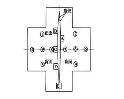
Figure 3 The schematic diagram of sampling locations
2.3 Hardness measurement
The hardness of the positions shown in Figure 3 was measured and the results are shown in Table 1. The hardness values of most locations inspected were abnormally high, and some parts even exceeded HB300, which exceeds the normal hardness value of 0Cr18Ni9.
Table 1 The results for the hardness test
1. Overview
A stainless steel tee in an acid water industrial pipeline of a coal chemical plant cracked and failed. The operating pressure of the pipeline is 0.6MPa; the operating temperature is between 60 and 70℃; the medium is acid water. The material of the cracked tee is 0Cr18Ni9 (SH3408-96) with a specification of 89mm × 4.0mm.
2. Inspection
2.1 Macro inspection
A macro inspection of the tee showed that there was no obvious pitting or other thinning caused by corrosion in any area. The crack position is located in the middle of the tee, which is a bit away from the welding seam area. The crack is big; the width of the opening is wide, and the cracks are straight and have a few branches. There are multiple cracks on the front of the tee, and the crack at the back is a single crack. There was no obvious deformation except for the crack tip at the back. See Figure 1 and Figure 2.
Figure 1 The front of the cracked stainless steel tee Figure 2 The back of the cracked stainless steel tee
2.2 Detection and sampling locations
The schematic diagram of the tee is shown in Figure 3, and the detection and sampling locations are shown in Figure 3, among which ① to ⑩ are the hardness test locations. A is the fracture sampling location for scanning electron microscopy and energy spectrum analysis. B, C and D are the sampling parts for the metallographic analysis of the base material. E is the sampling location of the crack tip of the metallographic analysis. The base material part from the remaining material of the above-mentioned sampling locations is used for the analysis of chemical composition.
Figure 3 The schematic diagram of sampling locations
2.3 Hardness measurement
The hardness of the positions shown in Figure 3 was measured and the results are shown in Table 1. The hardness values of most locations inspected were abnormally high, and some parts even exceeded HB300, which exceeds the normal hardness value of 0Cr18Ni9.
Table 1 The results for the hardness test
| Positions | Measurement results (HB) | ||||
| 1 | 258 | 256 | 269 | 286 | 255 |
| 2 | 237 | 210 | 219 | 219 | 237 |
| 3 | 270 | 280 | 270 | 285 | 270 |
| 4 | 271 | 287 | 273 | 283 | 277 |
| 5 | 272 | 286 | 275 | 272 | 266 |
| 6 | 318 | 295 | 313 | 309 | 308 |
| 7 | 280 | 279 | 253 | 272 | 249 |
| 8 | 198 | 194 | 227 | 218 | 197 |
| 9 | 297 | 270 | 307 | 278 | 299 |
| 10 | 299 | 279 | 301 | 304 | 284 |
Table 2 Testing results of the chemical composition of tees' base metal
| Chemical composition % | Requirements of GB/T 14976-2002 (Smelting analysis) | Test results of tees' base metal |
| C | ≤0.07 | 0.023 |
| Si | ≤1.00 | 0.54 |
| Mn | ≤2.00 | 1.20 |
| P | ≤0.035 | 0.038 |
| S | ≤0.030 | 0.0048 |
| Ni | Between 8.00 and 11.00 | 8.60 |
| Cr | Between 17.00 and 19.00 | 16.60 |
2.4 The chemical composition analysis of materials
From the results of the macro inspection, it can be seen that the crack is far away from the welding seam area; the influence of welding on the cracked part is not considered, so only the chemical composition of the base material is analyzed. The results are shown in Table 2. At the same time, the requirements of the chemical composition of the 0Cr18Ni9's grades in SH 3408—96 are listed. It can be seen from the comparison that the content of Р element is slightly higher than the standard, while that of Cr element is lower than the lower limit of the standard.
2.5 Metallographic analyses
According to the positions shown in Figure 3, samples were taken at B, C, D and E for metallographic analyses. The results are shown in Figures 4 to 7. According to the requirements of SH3408-96, this material should be at a phase state of an austenitic structure after solution treatment when it is supplied. A lot of non austenite structure can be observed from the metallographic analysis, and the traces of drawing and rolling of pipes are very obvious. The direction of the cracking is consistent with the rolling direction. Obvious martensite structure can be seen in the 4 sampling positions, leading to the increase in strength of materials, which is consistent with the results of the hardness test. Although martensite can increase the strength of the material, its toughness is low and its corrosion resistance is worse than that of austenitic stainless steel. Use a magnet to stick to the different parts of the tee and an obvious magnetization reaction can be seen, which also proves that the material of the tee is not pure austenite phase state.
Post URL: https://www.landeepipefitting.com/failure-analysis-of-the-cracking-of-stainless-steel-tees-in-industrial-pipelines-part-one.html
Landee is a professional industrial pipe fitting manufacturer and be well accepted by customers all over the world, we has been producing Pipe Fitting for a variety of applications since 1985. welcome to access our website: https://www.landeepipefitting.com.
Previous: Scouring and Wear of Elbows
Next: Failure Analysis of the Cracking of Stainless Steel Tees in Industrial Pipelines (Part Two)
Next: Failure Analysis of the Cracking of Stainless Steel Tees in Industrial Pipelines (Part Two)
