Leakages of Hydrogen Pipeline in Refining and Chemical Hydrogen Production Units
Posted: 08/10/2023 07:20:01 Hits: 43
Summary
In refining and chemical enterprises, with the development of enterprises and market demand, the national and international requirements for gasoline and other product standards continue to increase, and the number of hydrogenation units continues to increase; the demand for hydrogen continues to increase. Hydrogen production units are in production, and the probability of failure has greatly increased.
1. Introduction of failures
In the inspection process of the hydrogen production unit personnel of a refining and chemical company, they found that there was abnormal sound in the pipeline area from desuperheater II to F-301-1. During the inspection, it was observed that there was water dripping and water vapor was intermittently ejected at the outlet of the desuperheater II. After conducting safety risk identification, taking safety precautions and starting relevant emergency plans, relevant personnel removed and inspected the insulation of this section of pipe fittings, and found that the reducer body of DN400×DN300 in the pipeline 400-P-22133005 cracked and leaked, with a size of about 150mm (Figure 1). According to the situation of the leakage, the relevant management personnel made an on-site study and decided to arrange an immediate shutdown and organize related operations such as emergency repairs.
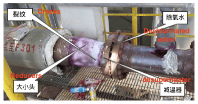
Figure 1 Cracking of the reducer
2. The background of equipment
The hydrogen production unit is a supporting project of a refinery company's centralized crude oil processing and refinery structure adjustment technical transformation project. It belongs to the E and PC construction. It is designed by a design institute and a PC general contractor. The hydrogen production unit uses coking dry gas, hydrogenated dry gas, low fraction gas, and styrene tail gas as raw materials, and the final product is hydrogen. The product hydrogen is used as the hydrogen source for 180 × 104t/a diesel hydrofinishing and 200×104t/a hydrocracking units. The nominal scale of the hydrogen production unit is 60000 Nm per hour (6 x 10⁴Nm3/h).
The reducer of the pipeline 400-P-22133005-5K1 of the conversion unit cracked and failed after about one and a half years of operation. The design file shows that the design parameters of the reducer are 0Cr18Ni10Ti, BW, SMLS. GB14976, CON, SH3408, 13mm (L)×Sch 40s (S), and the reducer has a size of DN400×DN300. The design operating temperature is 420°C; the operating pressure is 3.5MPa, the actual operating temperature is 360°C; the operating pressure is 2.6MPa. The internal medium of the reducer is a mixed gas, in which the steam content is about 81%, the hydrocarbon content is about 16%, and contains a small amount of CO, CO2 and H2. The pipeline with failure is 400-P-22133005, which has a total length of 10.6 meters and a wall thickness of 13mm, and is made from 0Cr18Ni10Ti. The transport medium is a mixed gas, containing hydrogen, methane, carbon monoxide, carbon dioxide and water vapor.
The main process flow of this part is in Figure 2. The gas is first pressurized by the feed gas compressor; enters the E302 shell layer, and exchanges heat with the shift gas in the tube layer. After the temperature rises, it enters the hydrogenation reactor R201 through the 200-G-22132001-5F1 pipeline, and enters the desulfurization tank R202A/B through the 200-G-22132003-5F1 pipeline after the hydrogenation reaction; desulfurizes the raw material gas. After coming out from the desulfurization tank R202A/B, the gas goes through the 200-G-22132009-5F1 pipeline and the superheated steam in the 250-MS-22133023-5F1 pipeline, merging to 300-P-22132004-5K1, and entering the 2213-X-302 desuperheater II. After the desuperheater II is the pipeline 400-P-22132005-5K1, where the failure of the reducer of DN400×DN300 is located. The raw material gas mixture enters the mixed gas preheater in the convection section of the F-301-1 reformer through the 400-P-22133005-5K1 pipeline, and enters the reformer F-301 for reaction after heat exchange.
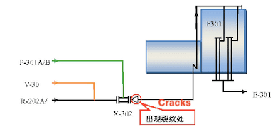
Figure 2 The process flow chart
In refining and chemical enterprises, with the development of enterprises and market demand, the national and international requirements for gasoline and other product standards continue to increase, and the number of hydrogenation units continues to increase; the demand for hydrogen continues to increase. Hydrogen production units are in production, and the probability of failure has greatly increased.
1. Introduction of failures
In the inspection process of the hydrogen production unit personnel of a refining and chemical company, they found that there was abnormal sound in the pipeline area from desuperheater II to F-301-1. During the inspection, it was observed that there was water dripping and water vapor was intermittently ejected at the outlet of the desuperheater II. After conducting safety risk identification, taking safety precautions and starting relevant emergency plans, relevant personnel removed and inspected the insulation of this section of pipe fittings, and found that the reducer body of DN400×DN300 in the pipeline 400-P-22133005 cracked and leaked, with a size of about 150mm (Figure 1). According to the situation of the leakage, the relevant management personnel made an on-site study and decided to arrange an immediate shutdown and organize related operations such as emergency repairs.
Figure 1 Cracking of the reducer
2. The background of equipment
The hydrogen production unit is a supporting project of a refinery company's centralized crude oil processing and refinery structure adjustment technical transformation project. It belongs to the E and PC construction. It is designed by a design institute and a PC general contractor. The hydrogen production unit uses coking dry gas, hydrogenated dry gas, low fraction gas, and styrene tail gas as raw materials, and the final product is hydrogen. The product hydrogen is used as the hydrogen source for 180 × 104t/a diesel hydrofinishing and 200×104t/a hydrocracking units. The nominal scale of the hydrogen production unit is 60000 Nm per hour (6 x 10⁴Nm3/h).
The reducer of the pipeline 400-P-22133005-5K1 of the conversion unit cracked and failed after about one and a half years of operation. The design file shows that the design parameters of the reducer are 0Cr18Ni10Ti, BW, SMLS. GB14976, CON, SH3408, 13mm (L)×Sch 40s (S), and the reducer has a size of DN400×DN300. The design operating temperature is 420°C; the operating pressure is 3.5MPa, the actual operating temperature is 360°C; the operating pressure is 2.6MPa. The internal medium of the reducer is a mixed gas, in which the steam content is about 81%, the hydrocarbon content is about 16%, and contains a small amount of CO, CO2 and H2. The pipeline with failure is 400-P-22133005, which has a total length of 10.6 meters and a wall thickness of 13mm, and is made from 0Cr18Ni10Ti. The transport medium is a mixed gas, containing hydrogen, methane, carbon monoxide, carbon dioxide and water vapor.
The main process flow of this part is in Figure 2. The gas is first pressurized by the feed gas compressor; enters the E302 shell layer, and exchanges heat with the shift gas in the tube layer. After the temperature rises, it enters the hydrogenation reactor R201 through the 200-G-22132001-5F1 pipeline, and enters the desulfurization tank R202A/B through the 200-G-22132003-5F1 pipeline after the hydrogenation reaction; desulfurizes the raw material gas. After coming out from the desulfurization tank R202A/B, the gas goes through the 200-G-22132009-5F1 pipeline and the superheated steam in the 250-MS-22133023-5F1 pipeline, merging to 300-P-22132004-5K1, and entering the 2213-X-302 desuperheater II. After the desuperheater II is the pipeline 400-P-22132005-5K1, where the failure of the reducer of DN400×DN300 is located. The raw material gas mixture enters the mixed gas preheater in the convection section of the F-301-1 reformer through the 400-P-22133005-5K1 pipeline, and enters the reformer F-301 for reaction after heat exchange.
Figure 2 The process flow chart
Post URL: https://www.landeepipefitting.com/leakages-of-hydrogen-pipeline-in-refining-and-chemical-hydrogen-production-units.html
Landee is a professional industrial pipe fitting manufacturer and be well accepted by customers all over the world, we has been producing Pipe Fitting for a variety of applications since 1985. welcome to access our website: https://www.landeepipefitting.com.
Previous: Analysis & Preventive Measures for Cracks in Ultra-high Pressure Steam Pipelines
Next: Inspection of Hydrogen Pipelines in Refining and Chemical Hydrogen Production Units
Next: Inspection of Hydrogen Pipelines in Refining and Chemical Hydrogen Production Units
