The Connection Scheme between Reducers of Heat Exchangers and Pipes
Posted: 05/09/2022 07:45:34 Hits: 68
Abstract: When a chemical plant is overhauled, two sets of overlapping fixed tube sheet heat exchangers are replaced. The carbon steel flanges at the inlet and outlet of the tube box are of different materials and specifications than the external stainless steel pipelines. In order to ensure that the device starts up as soon as possible, use the stocked carbon steel reducer to connect the flange and the external pipeline. By optimizing the connection structure, and adopting reasonable welding materials and welding processes, the quality of the welding of dissimilar steels is ensured.
1. Optimization of the connection structure scheme
The main body has a length of 7016mm. The shell side medium is steam condensed water. The working pressure is 0.1MPa, and the shell side medium is demineralized water; the working pressure is 1.0MPa. The inlet and outlet flanges of the pipe box and the matching flange are made of carbon steel 20, and the material of the external pipeline connected to the matching flange is stainless steel 304. The pipe box outlet flange and mating flange of these two heat exchangers have a size of DN150mm due to design problems, and the connected stainless steel pipeline is DN250mm. It is necessary to connect the mating flange to the external pipeline through a reducer, as shown in Figure 1.
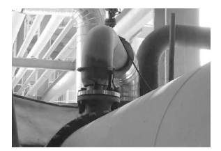
Figure 1 The outlet mating flange and the dissimilar steel of the external pipeline connected by a reducer
1.1 The reducer arranged in the horizontal pipeline position
To ensure that the device starts up as soon as possible, the initial plan is to use a stocked elbow made of carbon steel with DN150mm and a reducer with DN150mm or 250mm to connect with the matching carbon steel flange and the original stainless steel pipeline. At this time, the dissimilar steel welding seam of the reducer and the carbon steel elbow and the carbon steel butt welding flange are each with a ring seam of the same material, as shown in Figure 2.
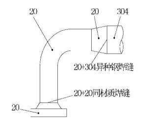
Figure 2 The reducer arranged in the horizontal pipeline position
According to this connection scheme, the stocked pipe section is directly used, and the welding seam of the original pipe section does not need to be cut. However, the welding seam between dissimilar steels is located in a horizontal fixed position at this time, which requires good operating skills, and the welding quality is not easy to guarantee. In addition, the use of concentric reducers on horizontal pipelines is easy to accumulate materials. According to SH/T3012-2011 Design Specifications of Petrochemical Metal Pipelines, it is recommended to use eccentric reducers on horizontal pipelines.
1.2 The reducer arranged in the vertical pipeline position
The reducer is moved to the butt welding flange, and the welding joint between dissimilar steels is located in the horizontal welding position, which is convenient for the welder to operate, control the welding heat input, ensure the quality of the welding, and avoid the accumulation of materials in the reducer. At this time, it is necessary to cut the annular seam between the reducer and the original pipe section and weld the connecting flange and stainless steel pipeline, which results in more preparation work than the reducer arranged in a horizontal position, as shown in Figure 3.
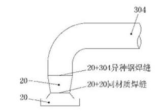
Figure 3 The reducer arranged in the vertical pipe position
2. The analysis of weldability of dissimilar steel between carbon steel 20 reducers and stainless steel 304 pipelines
Compared with carbon steel, austenitic stainless steel 304 has a small thermal conductivity and a great coefficient of linear expansion. Under the conditions of partial uneven heating and cooling in the welding process, if the welded joint stays at a high temperature for too long, it will bear great tensile stress. The welding seam of austenitic stainless steel 304 has a coarse columnar grain structure, and impurities such as sulfur and phosphorus are likely to form a low-melting liquid film in the welding seam. When the welding seam is solidified, it is easy to generate hot cracks due to the tensile stress of the joint.
Table 1 A comparison of typical physical properties of austenitic stainless steel 304 and carbon steel 20
1. Optimization of the connection structure scheme
The main body has a length of 7016mm. The shell side medium is steam condensed water. The working pressure is 0.1MPa, and the shell side medium is demineralized water; the working pressure is 1.0MPa. The inlet and outlet flanges of the pipe box and the matching flange are made of carbon steel 20, and the material of the external pipeline connected to the matching flange is stainless steel 304. The pipe box outlet flange and mating flange of these two heat exchangers have a size of DN150mm due to design problems, and the connected stainless steel pipeline is DN250mm. It is necessary to connect the mating flange to the external pipeline through a reducer, as shown in Figure 1.
Figure 1 The outlet mating flange and the dissimilar steel of the external pipeline connected by a reducer
1.1 The reducer arranged in the horizontal pipeline position
To ensure that the device starts up as soon as possible, the initial plan is to use a stocked elbow made of carbon steel with DN150mm and a reducer with DN150mm or 250mm to connect with the matching carbon steel flange and the original stainless steel pipeline. At this time, the dissimilar steel welding seam of the reducer and the carbon steel elbow and the carbon steel butt welding flange are each with a ring seam of the same material, as shown in Figure 2.
Figure 2 The reducer arranged in the horizontal pipeline position
According to this connection scheme, the stocked pipe section is directly used, and the welding seam of the original pipe section does not need to be cut. However, the welding seam between dissimilar steels is located in a horizontal fixed position at this time, which requires good operating skills, and the welding quality is not easy to guarantee. In addition, the use of concentric reducers on horizontal pipelines is easy to accumulate materials. According to SH/T3012-2011 Design Specifications of Petrochemical Metal Pipelines, it is recommended to use eccentric reducers on horizontal pipelines.
1.2 The reducer arranged in the vertical pipeline position
The reducer is moved to the butt welding flange, and the welding joint between dissimilar steels is located in the horizontal welding position, which is convenient for the welder to operate, control the welding heat input, ensure the quality of the welding, and avoid the accumulation of materials in the reducer. At this time, it is necessary to cut the annular seam between the reducer and the original pipe section and weld the connecting flange and stainless steel pipeline, which results in more preparation work than the reducer arranged in a horizontal position, as shown in Figure 3.
Figure 3 The reducer arranged in the vertical pipe position
2. The analysis of weldability of dissimilar steel between carbon steel 20 reducers and stainless steel 304 pipelines
Compared with carbon steel, austenitic stainless steel 304 has a small thermal conductivity and a great coefficient of linear expansion. Under the conditions of partial uneven heating and cooling in the welding process, if the welded joint stays at a high temperature for too long, it will bear great tensile stress. The welding seam of austenitic stainless steel 304 has a coarse columnar grain structure, and impurities such as sulfur and phosphorus are likely to form a low-melting liquid film in the welding seam. When the welding seam is solidified, it is easy to generate hot cracks due to the tensile stress of the joint.
Table 1 A comparison of typical physical properties of austenitic stainless steel 304 and carbon steel 20
| Materials | Thermal conductivity w/(m · K) | Linear expansion coefficient 10-6℃ |
| 304 | 16.29 | 17.8 |
| 20 | 46.89 | 11.5 |
To avoid welding hot cracks, it is necessary to control the content of impurities such as sulfur and phosphorus in the base metal, welding materials and welding environment, reduce the residence time of welded joints at high temperatures, and avoid forced assembly to reduce welding stress. Austenitic stainless steel 304 and carbon steel 20 dissimilar steel are different in chemical composition and microstructure and properties, and the following problems need to be solved in the welding of the two materials.
2.1 Cracks easily occurred due to dilution of welding seams
When welding austenitic stainless steel 304 and carbon steel 20 dissimilar steel, the welding seam metal is diluted by the ferritic carbon steel, which will produce brittle martensite in the transition zone of the welded joint, easily causing welding cracks. The brittle transition zone is unavoidable in the welding of dissimilar steels. Only by increasing the nickel content in the welding seam metal can the formation of austenite structure be promoted, reducing the martensite structure, the width of the brittle transition zone, and improving the toughness of the welded joint.
2.2 The impact of migration of carbon
When welding austenitic stainless steel 304 and carbon steel 20, if the welding joint stays at a high temperature for too long, serious migration of carbon will occur at the interface between pearlite and austenite, and softened decarburized will be formed on one side of ferritic steel and a hardened carburized layer on one side of the austenitic steel. The properties of the two sides are quite different, resulting in greater stress concentration and reducing the bearing capacity of the welded joint. To prevent the migration of carbon and reduce the dilution of pearlitic steel, the austenite transition layer is first welded on the ferritic steel during welding to control the heat input of the transition layer during welding and reduce the residence time of the welded joint at a high temperature, and welding stress.
2.3 Residual stress of welded joints
The welding process is a process of uneven heating under the action of the welding arc, and the uneven heating in different areas produces welding stress. For the welding of dissimilar steel, when the thermal conductivity and linear expansion coefficient of ferritic steel and austenitic steel on both sides of the welded joint are different, residual stress will generate due to different cooling shrinkage after welding.
To reduce the residual stress of the welded joint, the filler metal of the welding seam with a linear expansion coefficient similar to that of carbon steel 20 and good plasticity and high nickel content should be selected, so that the welding stress is concentrated on the side of austenitic stainless steel 304 with relatively good plasticity.
Post URL: https://www.landeepipefitting.com/the-connection-scheme-between-reducers-of-heat-exchangers-and-pipes.html
Landee is a professional industrial pipe fitting manufacturer and be well accepted by customers all over the world, we has been producing Pipe Fitting for a variety of applications since 1985. welcome to access our website: https://www.landeepipefitting.com.
Previous: Materials of Pipe Fittings for Resisting Hydrogen Sulfide Stress Corrosion
Next: The Connection between Reducers of Heat Exchangers & Dissimilar Steel Pipes
Next: The Connection between Reducers of Heat Exchangers & Dissimilar Steel Pipes
